GIS Based Load Flow Study for Distribution Network at Sihora Township
This undertaking work pertains to : “GIS based load flow survey for Distribution Network at Sihora township” .
Chapter 1: Introduction
In India, Power sector reforms are afoot chiefly to reconstruct efficiency and fiscal wellness in the sector and assorted SEBs have followed common form of reforms based on “World Bank Supported Orissa” theoretical account of ninetiess. Main nonsubjective covered under reforms are ; Unbundling of SEBs in to three separate sectors of Generation, Transmission & A ; Distribution and Corporatization of sectors. Added fiscal encouragement to the reforms procedure came in the signifier of “
Accelerated Power Development and Reform Program” ( APDRP )
and States willing to set about Distribution Reforms are eligible to pull financess in this strategy.Order custom essay GIS Based Load Flow Study for Distribution Network at Sihora Township with free plagiarism report
 450+ experts on 30 subjects
 Starting from 3 hours delivery
Distribution and Use of Power are 3rd and 4th sections of Integrated Power Systems and are unluckily weakest links as compared to Generation and UHV/EHV Transmission of Power because of high proficient and commercial losingss, overloading of Transformers and Feeders/Distributors and mass scale pilferage of power. Power Distribution nevertheless, assumes function of a gross gaining section of power system. Therefore, the existent challenge of reforms in Power Sector lies in efficient direction of Distribution and Utilization sections so that consumers get good power quality.
Power Sector Reforms initiated by Govt. of India, peculiarly in Distribution sector, are viewed as strong steps to better commercial and fiscal viability of this sector and the APDRP launched in the twelvemonth 2001 was launched chiefly to beef up Primary, Secondary and Tertiary Distribution Networks and decrease of Average Technical and Commercial Losses ( AT & A ; C Losses ) .Main aims of this plan screen
- Constitution of baseline informations.
- Renovation and modernisation of 33/11 & A ; 11/0.4 KV Sub-Stations.
- Decrease of AT & A ; C losingss
- Commercial viability.
- Decrease of outages & A ; breaks.
- Increase consumer satisfaction through beef uping & As ; up-gradation of Sub-Transmission & A ; Distribution web and by supplying good power quality.
1.1 Application of Geographic Information System ( GIS ) in Distribution Systems.
GIS is a computer- based system to assistance in the aggregation, care, storage, analysis, end product, and distribution of spacial informations and information. Geographic information Systems ( GIS ) and Network Analysis are quickly progressing Fieldss in recent old ages and remain most important application countries.
- G- Stands for geographic and it has something to make with geographics.
- I - Stands for information i. vitamin E, geographic information.
- S- Stands for system. GIS is an incorporate system of geographics and information tied together.
1.2 Role Of Gis In Distribution Reforms.
Distribution is a job country in any Electric Power Supply Utility in India chiefly because the Technical plus Commercial losingss are extortionately high, ( 50 - 55 % ) . GIS can assist cut down losingss and better energy efficiency through its part in the undermentioned countries of Distribution reforms:
- 100 % consumer metering and Automatic Meter Reading.
- Feeder & A ; Distribution Transformer metering: Installation of inactive ( electronic ) metres on all 11 KV surpassing feeders and distribution transformers.
- Effective Myocardial infarction: Both feeder and DT inactive metres record active energy, power factor and burden information which can be downloaded to a computing machine web to construct effectual MIS for speedy decision-making.
- Energy accounting: Energy received in each 11 kV sub-station and 11 KV out-going feeders, energy billed and T & A ; D losingss at each feeder and DT can be decently accounted for.
- Installation of capacitance Bankss & A ; web reconfiguration: Installation of capacitances at 11 & A ; 400 Volt degrees, reconfiguration of feeder/ Distributors & A ; DTs in such a manner as to cut down the length feeders/distributors thereby cut downing Technical losingss.
- High Voltage Distribution System ( HVDS ) : Installation of little energy efficient DTs providing power to 10 to 15 families merely, re-conductoring of overladen subdivisions, digital function of the full distribution system and burden flow surveies to beef up the distribution system.
1.3 GIS aid in accomplishing the above aims through assorted applications:
- Creation of consumer database and consumer indexing: Indexing of all LT & A ; HT consumers, so as to segregate consumers feeder-wise and DT-wise. The consumers are mapped utilizing GIS engineering and identified based on their alone electrical reference, called Consumer Index Number ( CIN ) .
- Function of Sub-transmission and Electrical Distribution Network: It is every bit of import to hold all the 33 KV substations, 11 KV feeders, DTs and LT feeders digitally mapped and geo-referenced.
- Load Flow Studies: Having completed the aforesaid undertakings, burden and consumer profiles can be studied and illations drawn for rectifying instabilities in the web.
- Load Prediction: GIS has proved itself an effectual tool in placing ideal location for proposed Sub-Stations, demand-side direction, Load prediction.
1.4 Case Study
GIS has been used as a tool to transport out Consumer indexing and Load Flow Studies for Primary and Secondary distribution Network at Sihora township, near Jabalpur, under the Poorv Kshetra Vidyut Vitran Company ( MPPKVVCL ) and I was associated with this survey. Both these surveies were conducted at the same time. Basic aim was to update consumer informations and program betterment in the Network and to make away with over-loading of transformers and feeders so as to accomplish an acceptable electromotive force profile i.e, to supply all L.T. & A ; H.T. Consumers electromotive force in the scope 6 % .
Following stairss are covered in the instance survey :
- Field work for placing assets or GPS Survey.
- Transportation of GPS Co-ordinates to Lat-Lon Co-ordinates utilizing iilwis package.
- Downloading of orbiter images utilizing Google Earth pro.
- Alliance of spacial informations.
- Forming Database.
- Conducting Load Flow Study.
Decision summarises the result of this survey.
Chapter 2: Literature Review
2.1 Review 1
“ Application of Geographic Information Systems and Global Positioning Systems in Human-centered Emergencies: Lessons Learned, Programme Implications and Future Research”by Reinhard Kaiser Centers for Disease Control CDC and Prevention ( CDC ) , Paul B. Spiegel CDC, Alden K. Henderson CDC, Michael L. Gerber CDC ( Published by Blackwell Publishing, 9600 Garsington Road, Oxford OX4 2DQ, UK and 350 Main Street, Malden, MA 02148, USA ) .
This paper discusses application of GIS & A ; GPS in human exigencies.
2.2 Review 2
International diary onNetwork Analysis in Geographic Information Science: Review, Assessment, and Projections ( Cartography and Geographic Information Science, Vol. 34, No. 2, 2007, pp. 103-111 ) byKevin M. Curtin.
This documents informs thatNetwork informations constructions were one of the earliest representations in geographic information systems ( GIS ) , and web analysis remains one of the most important and relentless research and application countries in geographic information scientific discipline.
2.3 Review 3
Gis And Network Analysis
( By Manfred M. Fischer Department of Economic Geography & A ; Geoinformatics Vienna University of Economics and Business Administration Rossauer Lande 23/1 A-1090 Vienna, Austria ) .
Writer has described that the information theoretical accounts and design issues which are specifically oriented to GIS-T, and identified several betterments of the traditional web informations theoretical account that are needed to back up advanced web analysis in a land transit context.
2.4 Review 4
Electrical Network Mapping and Consumer Indexing utilizing GIS
( By S P S Raghav Chairman and Managing Director UPCL, Dehradun and Jayant K Sinha Dy General Manager ( IT ) UPCL, Dehradun ) .
This paper analyzes the present power scenario and the function of GIS in spearheading the Distribution reforms processes to better the power industry’s viability.
2.5 Review 5
GIS Based Power Distribution System: A Case Study For The Bhopal City( Dr. Tripta Thakur, Dept. of Electrical Engineering, MANIT, Bhopal ) .
Asset function utilizing GPS and high declaration remote feeling images has been reported in this paper utilizing Arc GIS 9.1software.
Problem Definition
The East DISCOM, at Jabalpur identified few townships as pilot undertakings for system betterment where the bing distribution web were- haphazard, shabbily constructed and expanded in an unplanned mode. AT & A ; C losingss were extortionately high runing between 50-60 % . With this in position, the GPS based information was opted to make reliable informations base and transport out the burden flow survey for the web at 11kv degree to obtain electromotive force profile within the prescribed bound of ± 6 % and besides to place low electromotive force pockets.
Aims of Thesis
- Constitution of baseline informations.
- Renovation and modernisation of 33/11 & A ; 11/0.4 KV Sub-Stations.
- Decrease of AT & A ; C losingss.
- Improvement of Voltage Profiles.
- Commercial viability.
- Improved care - Decrease of outages & A ; breaks.
- Increase consumer satisfaction by supplying good quality power supply.
Chapter 3:Geographical Positioning System ( GPS )
GPS Facts
- Developed by Department of Defence as a military navigational tool.
- Systems birth was in the early 1970’s
- 24 Satellites revolving at high heights ( 11,000 stat mis ) First Satellite launched in 1978
- Became to the full operational in April 1995
- Useful dark & A ; twenty-four hours – rain or radiance
- Use of wireless moving ridges
- Accuracy depends on unit, some are accurate to a centimeter.
- There are 3 orbits – LEO ( long Earth orbit ) , MEO ( average Earth orbit ) and GEO ( geostationary Earth orbit ) . The GPS system is located in GEO orbit.
3.1 Geographic placement system ( GPS )
GPS is a world-wide radio-navigation system formed from a configuration of 24 orbiters and their land Stationss. It uses these `` semisynthetic stars '' as mention points to cipher places accurate to a affair of metres. These orbiters have really accurate redstem storksbills on board. The orbiters continuously send wireless signals towards Earth. These wireless signals are picked up by GPS receiving systems
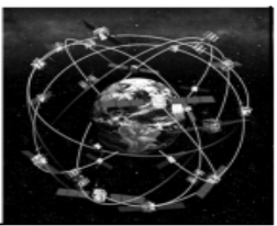
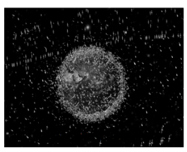
Figure - 1
GPS receiving systems have become really economical, doing the engineering accessible to virtually everyone. GPS provides uninterrupted 3-dimensional positioning 24 hours a twenty-four hours to the military and civilian users throughout the universe. These yearss GPS is happening its manner into autos, boats, planes, building equipment, farm machinery, even laptop computing machines. It has a enormous sum of applications in GIS informations aggregation, surveying, and function. GPS is progressively used for precise placement of geospatial informations and the aggregation of informations in the field.
 Figure - 2
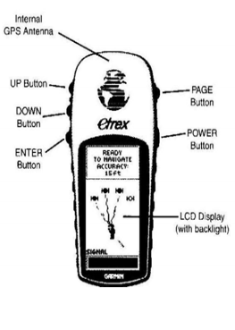
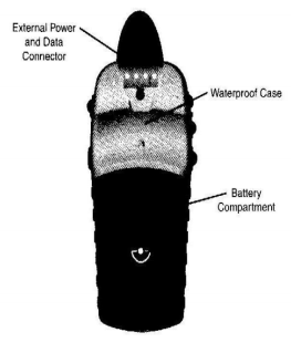
Figure - 3
3.2 GPS Control Stations
There are five control Stationss that monitor the orbiters.
- Control stations enable information on Earth to be transmitted to the orbiters ( updates and all right turning ) .
- Control Stationss continuously track orbiters, and update the places of each orbiter.
- Without control Stationss, the truth of the system would degrade in a affair of yearss.
3.3 GPS Receivers
- GPS units are referred to as “receivers” .
- hey receive information ( wireless signals ) from orbiters.
- The GPS receiving system is made of three parts ; I ) Satellites revolving the Earth two ) control and monitoring Stationss on Earth and three ) GPS receiving systems owned by users. GPS satellites send signals from infinite which are picked up and identified by GPS receiving systems. Each GPS receiving system so provides three dimensional location ( latitude, longitude, and height ) along with clip taken.
3.4 Three sections of GPS
The Space section:The infinite section consists of 20 four orbiters circling the Earth at an height of 12,000 stat mis. High height allows the signals to cover a big country. The orbiters are arranged in their orbits such that a GPS receiving system on Earth can ever have a signal from at least four orbiters at any given clip. Each orbiter transmits low wireless signals with a alone codification on different frequences. The GPS receiving system identifies the signals. The chief intent of these coded signals is to let for appraisal of travel clip from the orbiter to the GPS receiving system. The travel clip multiplied by the velocity of light peers the distance from the orbiter to the GPS receiving system. Since these are low power signals and won’t travel through solid objects, it is of import to hold a clear position of the sky.
The Control section: The control section tracks the orbiters and so provides them with corrected orbital and clip information. The control section consists of four remote-controlled control Stationss and one maestro control station. The four remote-controlled Stationss receive informations from the orbiters and so direct that information to the maestro control station where it is corrected and sent back to the GPS orbiters.
The User section:The user section consists of the users and their Global positioning system receiving systems. Number of users can hold entree at any minute of clip.
3.5 Working of GPS
When a GPS receiving system is turned on, it foremost downloads orbit information of all the orbiters. This processes, the first clip, can take every bit long as 12.5 proceedingss, but one time this information is downloaded, it is stored in the receiving systems memory for future usage. Even though the GPS receiving system knows the precise location of the orbiters in infinite, it still needs to cognize the distance from each orbiter it is having a signal from. That distance is calculated, by the receiving system, by multiplying the speed of the familial signal by the clip it takes the signal to make the receiving system. The receiving system already knows the speed, which is the velocity of a wireless moving ridge or 186,000 stat mis per second ( the velocity of visible radiation ) . To find the clip portion of the expression, the receiving system matches the orbiters transmitted codification to its ain codification, and by comparing them find how much it needs to detain its codification to fit the orbiters code. This delayed clip is multiplied by the velocity of visible radiation to acquire the distance. The GPS receiving systems clock is less accurate than the atomic clock in the orbiter, hence, each distance measuring must be corrected to account for the GPS receiving systems internal clock mistake.
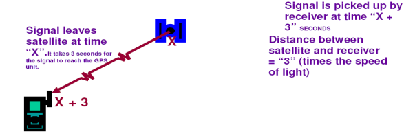
Figure – 3
3.6 GPS Terminology
2D Positioning: In footings of a GPS receiving system, this means that the receiving system is merely able to lock on to three orbiters which merely allows for a two dimensional place hole. Without an height, there may be a significant mistake in the horizontal co-ordinate.
3D Placement:Position computations in three dimensions. The GPS receiving system has locked on to 4 orbiters. This provides an height in a add-on to a horizontal co-ordinate, which means a much more accurate place hole.
Real Time Differential GPS: Real-time DGPS employs a 2nd, stationary GPS receiving system at a exactly measured topographic point ( normally established through traditional study methods ) . This receiving system corrects any mistakes found in the GPS signals, including atmospheric deformation, orbital anomalousnesss, Selective Availability ( when it existed ) , and other mistakes. A DGPS station is able to make this because its computing machine already knows its precise location, and can easy find the sum of mistake provided by the GPS signals. DGPS corrects or reduces the effects of:
- Orbital mistakes
- Atmospheric deformation
- Selective Handiness
- Satellite clock mistakes
- Receiver clock mistakes
DGPS can non rectify for GPS receiving system noise in the user’s receiving system, multipath intervention, and user errors. In order for DGPS to work decently, both the user’s receiving system and the DGPS station receiving system must be accessing the same orbiter signals at the same clip.
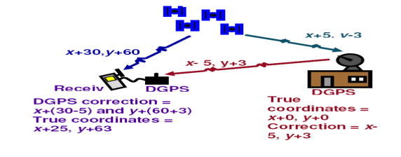
Figure – 4
Cite this Page
GIS Based Load Flow Study for Distribution Network at Sihora Township. (2018, Aug 26). Retrieved from https://phdessay.com/gis-based-load-flow-study-for-distribution-network-at-sihora-township/
Run a free check or have your essay done for you
