Design of Carburetors for Aircraft Application
Introduction
A carburetor is a constituent or device which largely used on reciprocating or Piston engine. They are an of import device which mixed or blends fuel and air for an internal burning of the engine. Internal burning engine refers to an engine in which burning is intermittent such as the more familiar four and two stroke Piston engines along with the discrepancies such as six stroke Piston engine.
Carburetors are classified as updraft or downdraft depending on the way of the air flow through the device. Most carburetors are the updraft type. All carburetors meter fuel and atomise it into the air to do a combustible mixture. In theory, the fuel/air mixture making each cylinder is indistinguishable in volume and ingestion. In world, both the volume and composing vary because the different distances travelled through the initiation manifold and force per unit areas exerted by the fumes system.
Order custom essay Design of Carburetors for Aircraft Application with free plagiarism report
 450+ experts on 30 subjects
 Starting from 3 hours delivery
Aircraft applications
New category of jobs for both engine and carburetor interior decorators created during the first aircraft engines, outside of those surface-bound vehicles. The chief complications were the deficiencies of apprehension of the temperature, force per unit area, air denseness, humidness, in add-on the velocity that these influence alterations while in flight. During 1918, the Bureau of Standards for the National Advisory Committee for Aeronautics accomplished a series of engine public presentation trials. The intent was to find the fluctuation in atmospheric force per unit area and temperature at assorted highs above the earth’s surface, with the alterations in public presentation ensuing from the variables within the carburetor itself and particular orientation to the variables impacting the operation of the carburetor. The study, published as Technical Report No. 48 in the NACA Fourth Annual Report, titled Carburetting Conditions Characteristics of Aircraft Engines, by Percival S. Tice. This work resulted in the undermentioned illations:
- The mixture ratio ( air/fuel ratio ) should be changeless at all heights for maximal power at all degrees.
- A alteration in fuel viscousness due to temperature alteration may be an of import metering feature of the carburetor.
- Constantly, there is wasted fuel when the carburetor does non rectify for barometric alterations.
- Heating of the fuel–air mixture causes a power loss accompanied by an addition in the specific fuel ingestion, with the available fuels.
A 2nd probe made by the Bureau of Standards between October 1919, and May 1923, reported in the tenth NACA Annual Report of 1924 as Technical Report No. 189, Relation of Fuel–air Ratio on Engine Performance, by Stanwood W. Sparrow, replies to the undermentioned inquiries:
- What fuel–air ratio gives maximal power?
- Does a alteration in air force per unit area or temperature, such as those encountered in flight, impact the value of this ratio appreciably?
- What per centum of its maximal power does an engine develop when supplied with a mixture giving minimal specific fuel ingestion?
The study concluded that:
- With gasolene as the fuel, fuel–air mixtures from 0.07 to 0.08 lbs fuel per pound. of air consequences in maximal power.
- Maximal power is obtained when about the same ratio is obtained over the scope of air force per unit areas and temperatures encountered in flight.
- Decreasing the fuel content of the charge until the power is 95 % of its maximal value provides the best specific fuel ingestion.
Principle
The carburetor works on Bernoulli 's rule which is the faster the air moves, the inactive force per unit area will be lower while the dynamic force per unit area will be higher. The accelerator or gas pedal linkage does non command the flow of liquid fuel straight. As an option, they really actuates the carburetor mechanisms which will meter the flow of the air as they were being pulled into the engine. Once carburetors are used on aircraft with reciprocating engines, characteristics and particular designs are required to forestall from fuel famishment during an upside-down flight.
Most manufactured carburetted as opposed to fuel-injected engines have a similar consumption manifold that transports and divides the fuel and air mixture to the consumption valves and a individual carburetor.
Older engines used updraft carburetors, where the air enters from below the carburetor and exits through the top of the carburetor. This gives rather a good advantage of ne'er `` deluging '' the engine, as any fuel droplets would fall out of the carburetors alternatively of into the consumption manifold ; it besides lent itself to utilize of an oil bath air cleansing agent, where a pool of oil below a mesh component below the carburetor is sucked up into the mesh and the air is drawn through the oil-covered mesh ; this was an effectual system in a clip when paper air filters did non be.
Get downing in the late 1930s, downdraft carburetors were the most popular type for automotive usage in the United States. In Europe, the side bill of exchange carburetors replaced downdraft as free infinite in the engine bay decreased and the usage of the SU-type carburetor ( and similar units from other makers ) increased. Some little propeller-driven aircraft engines still use the updraft carburetor design.
Outboard motor carburetors are typically side bill of exchange, because they must be stacked one on top of the other in order to feed the cylinders in a vertically oriented cylinder block.
The chief disadvantage of establishing a carburettor’s operation on Bernoulli 's Principle is that, being a fluid dynamic device, the force per unit area decrease in a Venturi tends to be relative to the square of the consumption air velocity. The fuel jets are much smaller and limited chiefly by viscousness, so that the fuel flow tends to be relative to the force per unit area difference. So jets sized for full power tend to hunger the engine at lower velocity and portion accelerator. Most normally this has been corrected by utilizing multiple jets. In SU and other movable jet carburetors, it was corrected by changing the jet size. For cold starting, a different rule was used in multi-jet carburetors. A flow resisting valve called a choking coil, similar to the accelerator valve, was placed upstream of the chief jet to cut down the consumption force per unit area and suck extra fuel out of the jets.
Carburetor
Carburetors are classified as updraft or downdraft depending on the way air flows through the device. Most carburetors are the updraft type. All carburetors meter fuel and atomise it into the air to do a combustible mixture. In theory, the fuel/air mixture making each cylinder is indistinguishable in volume and composing. In world, both the volume and composing vary because of the different distances travelled through the initiation manifold and force per unit areas exerted by the fumes system.
Principles OF CARBURETTORS VENTURI
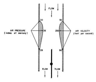

All carburetors depend on the differential force per unit area created by a Venturi to meter the proper sum of fuel for a volume of air. When air flows through a Venturi, its velocity additions while both force per unit area and temperature lessening. To command the volume of air that passes through a Venturi, all carburetors are equipped with a throttle valve. The throttle valve ( or butterfly valve ) is a pilot-controllable restrictor home base installed between the Venturi and the engine. When the accelerator valve is to the full opened ( parallel to the air flow ) , the maximal volume of air and fuel enter the engine. In this instance, the lone constituent that limits the volume of air come ining the engine is the Venturi. However, as the accelerator valve is moved to its closed place ( perpendicular to the air flow ) less air is admitted and engine power is reduced. The size and form of the Venturi is designed for the demands of the engine. Carburetors on similar engines might look to be indistinguishable, but the size of the Venturi could be different. Always guarantee that you are put ining the right device on an engine.
Figure 1 shows when the accelerator valve is parallel to the air flow, the maximal volume of air and fuel enters the engine. When the accelerator valve is near perpendicular to the air flow, less air and fuel enter the engine.
The system of carbubettor
To supply an engine with the necessary fuel for proper operation under assorted engine tonss, velocities, and air densenesss, most carburetors include the undermentioned five systems:
- Main metering
- Idling
- Mixture control
- Accelerating
- Power enrichment or economiser
The building and rule of operation of each of these systems varies depending on the type of carburetor. The undermentioned subjects describe each system in relation to its usage in float-type and pressure-injection carburetors. The size and form of the Venturi is designed for the demands of the engine. Carburetors on similar engines might look to be indistinguishable, but the size of the Venturi could be different. Always guarantee that you are put ining the right device on an engine.
The float - type carbubetors
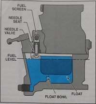
The float-type carburetor is named after the constituent used to modulate the fuel that enters the carburetor. Fuel is stored in a float chamber, the sum controlled by a float-operated needle valve installed in the fuel recess. As fuel enters the chamber, the float rises and the needle valve begins to shut. After the fuel reaches an established degree, the place of the float wholly closes the needle valve and the flow of fuel Michigans.
The carburetor float is typically constructed of brass or a composite stuff. Brass floats are hollow, and the air sealed indoors provides perkiness. A composite float can be hollow or solid. When the float solid, air trapped in the pores of the composite stuff provides perkiness.

As the volume of fuel alterations in a float chamber, the volume of air besides changes. A blowhole maintains ambient force per unit area in the float chamber as the fuel degree rises and falls. All float Chamberss are vented to ambient force per unit area.
In figure 2, the float carburetors store a measure of fuel in a float chamber. The sum of fuel in the float chamber is controlled by a float-actuated needle valve.
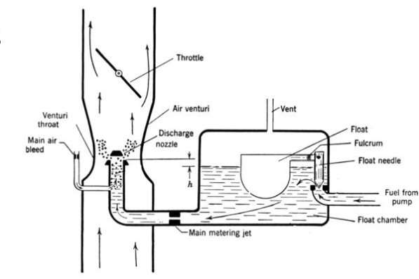
Figure 3
The figure 3 above visualize of the Float Level, Main Metering Jet and Discharge Nozzle. Please be reminded that the fuel degree in the fuel bowl is somewhat below the fuel discharge nozzle gap and is identified by the missive ‘h’ .
The basic aircraft fuel system
The fuel circuit includes the parts and shrieking necessary to present fuel to the carburetor fuel recess, at the proper force per unit area and volume. The fuel admitted through the float-type carburetor recess valve is reduced to atmospheric force per unit area as the fuel bowl blowhole to the air recess canal.
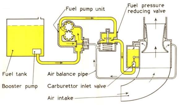
Figure 4
As the fuel bowl fills, the float rises with the fuel degree until the fuel degree in the fuel bowl is somewhat below the degree of the discharge nose and one time at the right degree, the float is high plenty to shut the recess valve, halting fuel flow into the carburetor at a precise tallness. This prevents fuel leaks into the consumption manifold when the engine is non running. Fuel can non come in the consumption system unless consumption manifold suction is sufficiently strong plenty to raise the fuel up to the tallness of the discharge nozzle gaps. On its manner to the discharge nose, extra jets control the rate of fuel flow and force per unit area, as necessary. The bead in fuel force per unit area through the recess valve classifies the valve as a jet.
Main matering of float type carburettor
The chief metering system supplies the engine with the right sum of fuel for all velocities above idle. The system consists of one or more venturi tubings, the chief metering jet and discharge noses, and the throttle valve.
Fuel metering begins at the Venturi. In some carburetors, a individual Venturi is deficient to make an equal force per unit area bead to meter fuel. In this instance, a encouragement Venturi is installed frontward of the primary Venturi.
The discharge nozzle delivers fuel from the float chamber to the consumption air. For an engine at remainder, the fuel in the discharge nose is even with the degree in the float chamber. In most instances, the fuel degree is about 1/8 inch below the gap of the discharge nose. This distance is referred to as the fuel metering caput and is designed to forestall fuel from leaking from the carburetor when the engine is non runing.
Cite this Page
Design of Carburetors for Aircraft Application. (2018, Sep 01). Retrieved from https://phdessay.com/design-of-carburetors-for-aircraft-application/
Run a free check or have your essay done for you
