Design of Industrial Robots
Abstraction
Today, industrial automaton is used in assorted intents such as welding, picture, choice and topographic point, production review, and proving. Because of its popular, industrial automaton has become interesting field, many companies, research centres and scientists spend much of money, clip to better features of industrial automaton. Simulation is a cardinal competency for both robot makers, users and scientists to better automaton public presentation, safety and cut down automaton cost, power, clip.
In this thesis, brief kinematics, kineticss and control theory are mentioned ; equations from these theories are applied for R-R and R-R-R operator, so these consequences are compared with simulation consequences to verify simulation consequences. In add-on, a simple existent theoretical account is built with 2 dynamixel servo motors ; the existent theoretical account can make simple work such as traveling point to indicate, following consecutive line.
Order custom essay Design of Industrial Robots with free plagiarism report
 450+ experts on 30 subjects
 Starting from 3 hours delivery
The simulations of automaton operator are performed by Recurdyn-Colink and Recurdyn-Matlab/Simulink. Forward and reverse kinematics are used to simulation automaton operator to execute progress trajectory way, the consequences from these simulations are used in kineticss subdivision. PD feedforward control besides is indicated, the control system based on independent articulation control, which frequently is known as single-input/ single-output system. These consequences from simulation are tantamount with theory. These consequences besides provide a batch of utile information for a batch of intents such as layout rating to avoid obstruction, optimisation flight way, kinematics, kineticss study.
Introduction
Motivation and history of industrial automaton
Today, we can run into industrial automaton in many mills in the universe. Applications of industrial automatons include welding, picture, choice and topographic point ( packing or SMT line ) , production review, and proving. Harmonizing to the International Federation of Robotics ( IFR ) , by the terminal of 2011, there were at least 1,153,000 operational industrial automatons. And IFR estimated the world-wide gross revenues of industrial automatons about US $ 8.5 billion. If cost of package, peripherals and systems technology are included, the industrial automaton market was estimated US $ 25.5 billion in 2011. Therefore, industrial automaton has been become an interesting field. Along with development of industrial automaton, simulation and theoretical account of industrial automatons are of import. They can supply a batch of utile information for many intents such as layout rating, kinematic, dynamic survey, off-line scheduling to avoid obstruction in the undertaking infinite and design mechanical construction of automatons.
The history of industrial automaton has associated with the development of computing machine aided design ( CAD ) and computing machine aided fabrication ( CAM ) systems. In 1954, George Devol applied for the first robotics patents ( granted in 1961 ) . In 1956, Devol and Joseph F. Engelberger formed the world’s foremost robot company was Unimation which was based on Devol’s original patents and Engelberger has been called as the male parent of robotics. Unimation has been built with hydraulic actuators and programmed in joint co-ordinates. The angle of each articulation was stored during a teaching stage and replayed in operation.
In the 70s the automaton industry increased really rapidly because of the tremendous investings by the automotive industry. In Europe, ABB Robotics and KUKA Robotics brought automatons to the market in 1973. ABB Robotics introduced IRB 6, it was become the first commercially operator which controlled all electric by micro-processor in the universe. The first two IRB 6 automatons were installed in production for crunching and smoothing pipe decompression sicknesss in 1974. In 1973 KUKA Robotics built its first automaton, FAMULUS, besides one of the first articulated automatons have driven six electromechanically axes. In US, many US companies entered the field, including elephantine companies such as General Electric, and General Motors ( a joint venture formed by General Motors and FANUC LTD of Japan called FANUC Robotics ) . Other companies besides started robotics concern such as Automatix and Adept Technology, Inc. In 1984, Unimation was acquired by Westinghouse Electric Corporation for 107 million U.S. dollars. After that Westinghouse sold Unimation to Staubli Faverges SCA of France in 1988, which is still doing articulated automatons for general industrial and cleanroom applications and even bought the robotic division of Bosch in late 2004.
Hardware and Software
During this thesis, three package ( RecurDyn, SolidWorks, Matlab ) have been used to work out this thesis assignment. Dynamixel servo motor besides was used for experimental intents.
RecurDyn V8R2
RecurDyn is developed by FunctionBay, Inc. which is a professional CAE company and provides MultiBody Dynamics ( MBD ) . RecurADyn is a modern CAE package suite which offers the alone combination of Multibody Dynamics, Finite Element Analysis and Controls.
Dynamic Rigid and Flexible Body Analysis to the full integrated additive and nonlinear Finite Element Analysis supply item information of realistic theoretical accounts for design surveies and bettering merchandise public presentation. By utilizing FE mesh, RecurDyn can imitate overall gesture every bit good as local distortions, strains and emphasiss.
RecurDyn CoLink, an incorporate signal flow oriented control design tool. It provides off-line simulation of mechatronic systems, traveling far beyond the classical Co-Simulation attack. If a elaborate Recurdyn multi flexible organic structure dynamic works theoretical account is used, the user can cut down the figure of cringles during the practical accountant parametric quantity optimisation procedure. In add-on, RecurDyn besides can link with Matlab/Simulink which has a batch of block libraries, plan linguistic communication tool, etc. for dynamic system.
Last but non least, RecurDyn has supported a batch of CAD package which are used as the Parasolid Kernel plan.
SolidWorks
SolidWorks is really popular 3D mechanical computing machine aided design package which runs on Microsoft Windows. It is established by Dassault Systemes SolidWorks Corp. It used Parasolid Kernel attack to make theoretical accounts and assemblies. Presently, over 2 million applied scientists and interior decorator usage SolidWorks at more than 165000 companies in whole universe.
Matlab
MATLAB is a numerical computer science environment and fourth-generation scheduling linguistic communication including C, C++ , Java, and FORTRAN. Established and developed by MathWorks, MATLAB is good known for matrix uses, plotting of maps and informations, creative activity of user interfaces, and interfacing with plans written in other linguistic communications.
In add-on, Simulink is an add-on merchandise with block libraries, informations flow graphical plan linguistic communication tool for mold, simulation, and analysing multi-domain dynamic and embedded systems.
Dynamixel
DYNAMIXEL is a consecutive high public presentation networked actuators for automatons developed by ROBOTIS. DYNAMIXEL can be used for multi-joint robot systems such as robotic weaponries, robotic manus, bi-pedal automaton, hexapod automaton, snake automaton, kinematic art, animatronics and mechanization, etc... DYNAMIXEL can be controlled utilizing Personal computer through USB2Dynamixel by many package such as Matlab, python, Microsoft Visual Studio ( C++ , C # ) , Visual Basic, Java, LabVIEW, occultation, ROS ( TTL/RS485/RS232 communicating ) . DYNAMIXEL besides can be controlled utilizing sole accountant such as CM-5 ( ATMega128 ) , CM-700 ( ATMega2561 ) , CM-510 ( ATMega2561 ) , CM-530 ( ARM Cortex M3 ) .
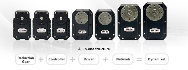
Fig1. Dynamixel servo motor
- Outline
- part
Chapter 2. Background theory
Positions, Orientations, and Frames
Position
In a co-ordinate system, any point can place with a 3x1 place vector in the existence. The place of point P in co-ordinate system is ordered set of three Numberss.

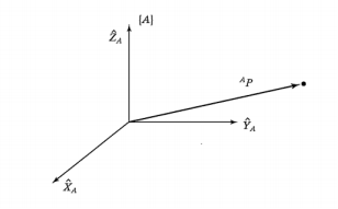
Fig2. Vector comparative to border { A }
Orientation
Frames
In robotics, the state of affairs of a place and an orientation brace arises so frequently is called a frame, which is a set of four vectors including one vector describes place and 3 vectors describe orientation.
The base frame, { B }
The base frame has place at the base of the automaton operator. It is appended to a unmoving portion of the automaton and frequently called link 0.
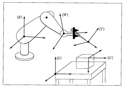
Fig3. The criterion frame
The station frame, { S }
The station frame has location in a task-relevant, in the figure above, it is at the corner of a tabular array which the automaton is to work, and all motions of the operator are implemented comparative to it. Sometimes, it is besides called as the existence frame, universe frame or the undertaking frame.
The carpus frame, { W }
The carpus frame { W } is fastened to the last nexus of the operator. { W } frequently has its beginning fixed at a point called the carpus of the operator, and { W } will travel with the last nexus of the operator.
The tool frame, { T }
The tool frame { T } is appended to the terminal of any tool the automaton happens to be keeping. { T } is normally located with its beginning between the fingertips of the automaton when the manus is empty.
The end frame, { G }
The end frame has location to which the automaton is to travel the tool. At the terminal of the gesture, the tool frame should be brought to happenstance with the end frame.
Chapter 3
Operator Kinematicss
Kinematicss is the scientific discipline of gesture including the place, the speed, the acceleration, and all higher order derived functions of the place variables. This chapter has 4th subdivisions: the Denavit-Hartenberg ( D-H ) parametric quantities, the forward kinematics, the opposite kinematics, the Jacobian.
Denavit-Hartenberg
Any robot operator can be described kinematically by the values of four measures for each nexus. Two describe the nexus itself, and two describe the link’s connexion to a adjacent nexus. The definition of mechanisms by 4th measures is a convention normally called the Denavit-Hartenberg notation.
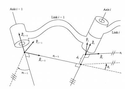
Fig4. Description of D-H parametric quantities
aI= the distance from ZIto Zi+1measured along TenI
 = the angle from ZIto Zi+1measured about TenI
vitamin DI= the distance from Teni-1to XImeasured along ZI
 = the angle from Teni-1to XImeasured about ZI
Forward Kinematicss
Forward kinematics is used to calculate the place and orientation of the tool frame from joint parametric quantities.
The transmutation from frame { one } to border { i-1 }
 ( 3.1 )
The nexus transmutations is multiplied together to happen the individual transmutation that relates frame { N } to border { 0 }
 ( 3.2 )
R-R operator forward kinematics
Lengths of two links are L1 and L2.
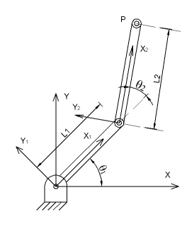
Fig5. R-R nexus frame assignment
| Link | I | aI | vitamin DI | I |
| 1 | 0 | 0 | 0 | 1 |
| 2 | 0 | Liter1 | 0 | 2 |
Table1. D-H parametric quantities of R-R operator
Computational transmutation matrices of each nexus
 ( 3.3 )
 ( 3.4 )
Therefore,
 ( 3.5 )
R-R-R operator forward kinematics

Fig6. R-R-R operator parametric quantities
| I |  |
 |
 |
 |
| 1 | 0 | 0 |  |
 |
| 2 | -90 | 0 | 0 |  |
| 3 | 0 |  |
 |
 |
| 4 | -90 |  |
 |
0 |
Table2. D-H parametric quantities of R-R operator
Transformation matrix for each nexus:
 ( 3.6 )
 ( 3.7 )
 ( 3.8 )
 ( 3.9 )
 ( 3.10 )
The transmutation matrix is gained by matrix generation of the single nexus matrices. At first,
 is gained by multiplying
 and
and

= ( 3.11 )

= ( 3.12 )
Finally

=
= ( 3.13 )
Here,
 ( 3.14 )
 ( 3.15 )
 ( 3.16 )
The matrix establishes the kinematics of R-R-R automaton operator ; it expresses the relationship between frame { 4 } and frame { 0 } about place and orientation.
Inverse Kinematicss
Inverse kinematics is survey of happening the needed articulation angles to put the tool frame, { T } , comparative to the station frame, { S } . The reverse kinematics job is well harder than the forward kinematics job. Unlike forward kinematics which ever exist solution, solution for reverse kinematics may non be. The being of a solution defines the workspace of a operator. If the exist solution, there can even be an infinite figure of solutions, for instant “elbow up” and “elbow down” solutions.
Using for R-R
Transformation from frame { 2 } to border { 0 } is mentioned by forward kinematics.

In frame { 2 } , the co-ordinate of point P is [ L20 0 1 ] . In the frame { 0 } , the co-ordinate of point P is [ten Y0 1 ] . Therefore

 ( 3.17 )
 ( 3.18 )
Square booth equations so add them:
 ( 3.19 )
 ( 3.20 )
 ( 3.21 )
 ( 3.22 )
Writingten, Yin the signifier
 ( 3.23 )
 ( 3.24 )
Where
 ( 3.25 )
 ( 3.26 )
If
 ( 3.27 )
And
 ( 3.28 )
Then
 ( 3.29 )
 ( 3.30 )
Equation ( 3.23 ) and ( 3.24 ) can be written as
 ( 3.31 )
 ( 3.32 )
So
 ( 3.33 )
 ( 3.34 )
Therefore,
 ( 3.35 )
Finally, equation for?1
 ( 3.36 )
See equation ( 3.22 ) , minus or plus gestural corresponds positions of R-R operator. In this state of affairs, “elbow up” and “elbow down” are mentioned.
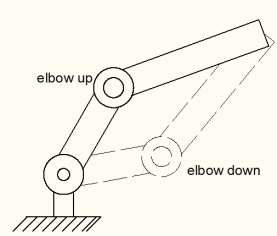
Fig7. Two positions of R-R operator
Using for R-R-R
From forward kinematics of R-R-R operator
So,
 ( 3.37 )
From equation ( 3.6 ) , Inverting matrix
 ( 3.38 )
Substitute in ( 3.37 )
 ( 3.39 )
So,
 ( 3.40 )
See about trigonometric permutations
 ( 3.41 )
 ( 3.42 )
Where
 ( 3.43 )
 ( 3.44 )
Using ( 3.41 ) and ( 3.42 ) , equation ( 3.40 ) can be written as
 ( 3.45 )
 ( 3.46 )
 ( 3.47 )
So
 ( 3.48 )
 ( 3.49 )
Finally, the solution for :
:
 ( 3.50 )
See elements ( 1,4 ) and ( 3,4 ) of the matrix in the right-hand of equation ( 3.39 )
 ( 3.51 )
 ( 3.52 )
Square both ( 3.51 ) and ( 3.52 ) so add the resulting equations
 ( 3.53 )
 ( 3.54 )
Or
 ( 3.55 )
Where
 ( 3.56 )
Equation ( 3.55 ) is of the same signifier as ( 3.40 ) so can be solved by the same method. Therefore, solution for is:
is:
 ( 3.57 )
So find solution for , consider:

 ( 3.58 )
 ( 3.59 )
Comparing both the ( 1,4 ) and ( 2,4 ) elements of matrix in right-hand of ( 3.59 )
 ( 3.60 )
 ( 3.61 )
These equations can be solved at the same time for and
and
 ( 3.62 )
 ( 3.63 )
From equation ( 3.62 ) and ( 3.63 ) ,
 ( 3.64 )
Because , therefore the concluding solution for
 is:
is:
 ( 3.65 )
The subtraction or plus mark in ( 3.50 ) and ( 3.57 ) do four possible position of operator.
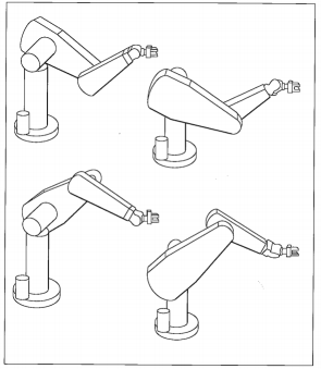
Fig8. Fourth positions of R-R-R operator
Jacobians
Relationship between the joint speed and the Cartesian speed is determined Jacobian

WhereVis a speed vector in Cartesian and ? is the vector of joint angles, J ( ? ) is Jacobian. The Jacobian has figure of rows is peers the figure of grade of freedom in the Cartesian infinite, and figure of columns is equal the figure of joint. For case, a general automaton with six articulations, The Jacobian is matrix of 6x6, is 6x1, and Cartesian speedVis 6x1with 3x1 additive speed vector and 3x1 rotational speed vector.
Example for R-R operator theoretical account
The Jacobian can be written a 2x2 matrix which relates joint speed to end-effector speed. The location of point P ( end-effector ) is (ten, Y) so, from equation ( 3.17 ) and ( 3.18 )
 ( 3.66 )
Derivative ( 3.66 )
 ( 3.67 )
Or
 ( 3.68 )
So, the Jacobian in frame { 0 } is
 ( 3.69 )
Other progress of Jacobian is invertible. From ( 3.70 ) , joint rate can be calculated with a certain speed vector in Cartesian co-ordinate. Note that most operators will hold values of ? where the Jacobian turns into singular.
 ( 3.70 )
Chapter 4 Manipulator Dynamics
In this chapter, equations of gesture for operator with torsions applied by actuators or external forces applied to the operator are mentioned.
Chpater 5 Trajectory and Control
Mentions
- John J. Craig, 2005, Introduction to Robotics Mechanics and Control, 3rded. , Pearson Education, Inc.
- Ahmed A. Shabana, 2005, Dynamics of Multibody Systems, 3rded. , Cambridge University Press.
- Reza N. Jazar, 2010, Theory of Applied Robotics Kinematics, Dynamics, and Control, 2neodymiumed. , Springer.
- RECURDYN, 2012, RecurDyn/ Solver Theoretical Manual, 8Thursdayed. , FunctionBay, Inc.
- Frank L.Lewis, Darren M.Dawson, Chaouki T.Abdallah, 2004, Robot Manipulator Control Theory and Practice, 2neodymiumed. , Marcel Dekker, Inc.
- Wikipedia
Cite this Page
Design of Industrial Robots. (2018, Aug 08). Retrieved from https://phdessay.com/design-of-industrial-robots/
Run a free check or have your essay done for you
