Code Division Multiple Access Communication Systems
Chapter 2- Communication System
Telecommunication systems have now made it possible to pass on with virtually anyone at any clip. Early telegraph and telephone system used Cu wire to transport signal over the earth’ surface and across oceans and high frequence ( HF ) wireless, besides normally called shortwave wireless, made possible inter-continental telephone links.Every communicating system has its ain frequence scope, system, capacity, application execution cost.
On the footing of transmittal system there are two types of communicating system
Order custom essay Code Division Multiple Access Communication Systems with free plagiarism report
 450+ experts on 30 subjects
 Starting from 3 hours delivery
• Wired communicating system
• Wireless communicating system
2.2 Multiple Access Technique
A limited sum of bandwidth is allocated for radio services. A radio system is required to incorporate as many users as possible by efficaciously sharing the limited bandwidth. Therefore, in communicating, the term multiple entree can non be defined as a agency of leting multiple users to at the same time portion the finite bandwidth with least possible debasement in the public presentation of the system.
There are four multiple entree methods -
a ) Frequency Division Multiple Access ( FDMA )
B ) Time Division Multiple Access ( TDMA )
degree Celsius ) Code Division Multiple Access ( CDMA )
vitamin D ) Space Division Multiple Access ( SDMA )
- Frequency Division Multiple Accesses ( FDMA )
FDMA is one of the oldest multiple entree techniques for cellular systems when uninterrupted transmittal is required for parallel services. In this bandwidth is divided into a figure of channels and distributed among users with a finite part of bandwidth for lasting usage, as illustrated in figure 2.2. The channels are assigned merely when there is a demand of the users. Therefore when a channel is non in usage it consequences in a otiose resource.
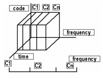
Fig 2.2Channel Use by FDMA
FDMA channels have narrow bandwidth of about 30 KHz, and therefore they are normally implemented in narrow set system. Since the user has his part of bandwidth all the clip, FDMA does non necessitate clocking control, which makes it simple. Even though no two users use the same frequence set at the same clip, guard sets are introduced between sets to minimise channel intervention. Guard sets are fresh frequence slots which separates neighbouring channels. This leads to a wastage of bandwidth. In a non-continuous transmittal bandwidth goes wasted since it is non being utilized for a part of the clip.
- Time Division Multiple Access ( TDMA )
In digital systems, uninterrupted transmittal is non required as the users do non use the allotted bandwidth all the clip. In such systems, TDMA is a O.K.ing technique compared to FDMA. Global Systems for Mobile communications i.e GSM uses the TDMA technique. In TDMA, bandwidth is available to the user but merely for a finite period of clip. In most instances the bandwidth is divided into fewer channels compared to FDMA and the users are allotted clip slots during which they have the full channel bandwidth at their disposal. This is illustrated in figure 2.3.
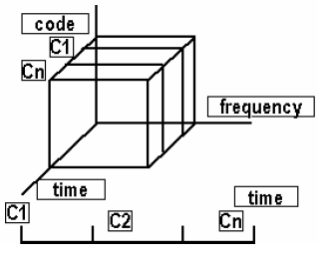
Fig 2.3Channel Uses by TDMA
TDMA requires careful clip synchronism since users portion the bandwidth in the frequence sphere. As the figure of channels are less, channel intervention is about negligible, hence the guard clip between the channels is significantly smaller. Guard clip is spacing clip between the TDMA. In cellular communications, whenever a user moves from one cell to other there is a opportunity that user could see a call loss if there are no free clip slots. TDMA uses different clip slots for transmittal every bit good as response.
- Code Division Multiple Access
In CDMA, all the users occupy the same bandwidth, though they are all assigned separate codifications, which distinguishes them from each other as shown in figure 2.4. CDMA systems utilize a spread spectrum technique in which a spreading signal, is uncorrelated to the signal and has a larger bandwidth, is used to distribute the narrow set signal. Direct Sequence Spread Spectrum i.e DS-SS is most normally used for codification division multiple surplus. In Direct sequence spread spectrum, the message signal is multiplied by a Pseudo Random Noise Code, which has a noise like belongingss. Each user has its ain codification which is extraneous to the codification of every other users. In order to feel the user, the receiving system is required to cognize the codeword used by the sender. contrasting TDMA, CDMA does non necessitate clip synchronism between the users.
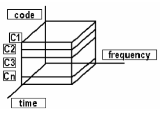
Fig 2.4Channel Uses by CDMA
2.4 CDMA
2.4.1 History
Code Division Multiple Access ( CDMA ) is a new construct in wireless communications. It has achieved widespread credence by cellular system operators, that will dramatically increase both their system capacity and the service quality. CDMA is a signifier of spread-spectrum, that have been used in military applications for old ages. The rule of spread spectrum is the usage of noise-like moving ridges and, as the name connote bandwidths much larger than that required for simple point to indicate communicating at the same information rate. foremost there were two motive: To defy enemy attempts to throng the communications ( anti-jam, or AJ ) , or to conceal the fact that communicating was even taking topographic point, from clip to clip called low chance of intercept. It has a history that goes back to the early yearss of World War second. The usage of CDMA for nomadic wireless applications is new. It was planned theoretically in the late fourty’s. profitable applications became promising because of two evolutionary developments. One was the handiness of really low cost, high denseness digital ICs, which cut down the size and cost of the endorser Stationss to an adequately low value.
Introduction to CDMA
CDMA is a multiple entree technique that allows multiple users to convey independent information within the same bandwidth at the same time. Each user is assigned a pseudo-random codification that is either extraneous to the codifications of all the other users or the codification possesses appropriate cross-correlation belongingss that minimize the multiple entree intervention ( MAI ) . This codification is superimposed on an information signal therefore, doing the signal emerges to be noise like to other users. Merely the intended receiving system has a reproduction of the same codification and uses it to pull out the information signal. This so allows the sharing of the same spectrum by multiple users without doing inordinate MAI. It besides ensures message privateness, since merely the intended user is able to “decode” the signal. This codification is besides known as a spreading codification, since it spreads the bandwidth of the original informations signal into a much higher bandwidth before transmittal.
2.4.2 CDMA Classification Tree
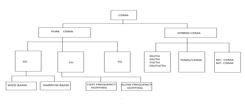
Fig 2.6Classification Tree of the assorted types of CDMA Techniques
Advantages of CDMA
One of the chief advantages of CDMA is that call dropouts occur merely when the phone is at least twice every bit far from the base station. It is used in the pastoral countries where GSM make non acquire to work decently. Another advantage is capacity means it has a really high spectral capacity so that it can suit more users.
Disadvantages of CDMA
One major job in CDMA engineering is channel pollution, where signals from excessively different cell sites are present in the subscriber’s phone but none of them is foremost. When this state of affairs arises the characteristic of the audio signal degrades. Another disadvantage is when compared to GSM it lacks international roaming capablenesss.
2.5 Spread Spectrum
Spread spectrum are the methods in which energy generated at a individual frequence is spread over a broad set of frequences. The basic spread spectrum technique is shown in Figure 2.7. This is done to accomplish transmittal that is robust against the channel damages, and to be able to defy natural interventions or thronging besides to forestall hostile sensing. These techniques were developed by military counsel systems. The technique is said to be spread spectrum if transmittal bandwidth is much greater than minimal bandwidth needed to convey the information.The system achieves spread spectrum if it fulfills the undermentioned demands:
- Signal occupies bandwidth much larger of the minimal bandwidth necessary to direct information.
- Spreading is done with the aid of distributing codification signal which is independent of the informations.
- At the receiving system, de-spreading is done by the correlativity of the received dispersed signal with a synchronised reproduction of the distributing signal used to distribute the information.

 Spread signal bandwidth

 Undesired signal


 informations signal


 recovered informations
Spreading code signal Spreading codification signal
Fig 2.7Model of Basic Spread Spectrum Technique
The chief parametric quantity in dispersed spectrum systems is the treating addition: Is the ratio of transmittal and information bandwidth:Gp = , which is fundamentally the spreading factor.
The processing addition calculates the figure of users that can be allowed, the sum of multi-path effects and the trouble to throng a signal.
Spread spectrum can be classified as follows –
a ) Direct Sequence Spread Spectrum
B ) Frequency Hoping Spread Spectrum
degree Celsius ) Time Hopping Spread Spectrum
2.5.1 DS-CDMA
Direct Sequence is the best Dispersed Spectrum Technique. The DS-CDMA method provides a multiple of benefits in cellular systems including easiness in planing frequence channels and protection against intervention, such that a high procedure addition is used. In DS-CDMA each user has its ain spreading codification. The choice of good codification is of import because auto-correlation belongingss and length of the codification restricts system capacity. The codification can be divided into two categories-
- Orthogonal codifications ( Walsh codifications )
- Non-orthogonal codifications ( PN, Gold, Kasami codifications )
The informations signal is multiplied by a Pseudo Random Noise Code. A PN codification is a sequence of french friess its scope is -1 and 1 ( polar ) or 0 and 1 ( non-polar ) . This consequences in low cross-correlation values among the codifications and the trouble to throng or observe a information message.
A usual manner to make a PN codification is by agencies of at least one displacement registry. The bit rate decides the rate at which distributing signals are transmitted. At the receiver terminal, spread signals are decoded with the aid of correlativity maps. Cross correlativity de-spreads the standard signals and retrieves the familial signal similar to the user’s original signal. The distributing sequences can orthogonal agencies ‘0’ transverse correlativity or random sequences with low cross-correlation belongingss.


 Y ( T )


 m ( T )
C ( T ) Cos ( wt )
Fig 2.8Direct Sequence Spread - Spectrum Modulation System
In the DS-CDMA technique, each spots of the users informations are multiplied with a codification in the transmitting terminal. The codification sequence used in conveying terminal performs the function of distributing codification.
The baseband theoretical account of a DS-CDMA system is shown in fig 2.8. Let m ( T ) denotes a binary information sequence, degree Celsius ( T ) denotes a codification sequence. The wave forms m ( T ) and c ( T ) denote polar representations in footings of two degrees as ±1. By multiplying the information spots by the codification, each information spot is divided into a little clip increases that are called french friess.
The baseband signal ( T ) is filtered to restrict energy within the bandwidth, defined by the codification rate. The bearer transition normally used in dispersed spectrum is phase displacement identifying. Sing the figure we get:
 ( T ) = m ( T ) C ( T ) ………………………………………………………………… ( 3.2 )
The baseband signal( T ) is convoluted with the impulse response of the spectrum determining filter to give Y ( T ) : Y ( T ) =( T ) ? H ( T ) , where * denotes convolution………………
The set base on balls signal ( T ) = [( T ) ? H ( T ) ] cos
 T ) …………………….. ( 3.4 )


 m ( T )


Cos ( wt ) Clock

C ( T )
Fig 2.9Matched Filter Spread-Spectrum Receiver.
The standard Band base on balls signal ( T ) is converted to an tantamount complex low base on balls signal A ( T ) by blending with a locally generated coherent bearer.
The complex low base on balls signal A ( T ) =( T ) cos t……………………….. ( 3.5 )
The de-spread signal B ( T ) = A ( T ) [ C ( T ) ? H ( T ) ] ………………………… ( 3.6 )
The end product of the matched filter D ( T ) =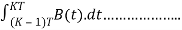 ( 3.7 ) .
The receiving system decodes the informations: D ( T ) & A ; gt ; 0 decode binary ‘1’ otherwise decode binary ‘0’.


 -11 1 1 -1 -1 1 -1 -1 1 1 1 -1 -1 1 -1 -1 -1

 user’s spot dispersed signal Despread signal Received spot

distributing sequence distributing sequence
Fig 2.10User Signal in DS-CDMA System
Let us believe the first spots of four users. By multiplying each spot with a PN codification, users spots are represented by seven french friess as shown above.
User 1 [ 1 ] : 1 C1: -1 -1 1 1 1 -1 1 = & A ; gt ; -1 -1 1 1 1 -1 1
User 2 [ 1 ] : -1 C2: 1 -1 -1 1 1 1 -1= & A ; gt ;-1 1 1 -1 -1 -1 1
User 3 [ 1 ] : 1 C3: -1 1 -1 -1 1 1 1 = & A ; gt ; -1 1 -1 -1 1 1 1
User 4 [ 1 ] : -1 C4: 1 -1 1 -1 -1 1 1
= & A ; gt ; -1 1 -1 1 1 -1 - 1
R [ 1 ] : -4 2 0 0 2 -2 2 ( received informations )
The received information consists of information of four users. To retrieve the original spots of users from the received informations, the received informations should multiplied with the codification sequence in the receiving system that is precisely same with that is used for distributing the original informations in sender agencies ( de-spreading ) . We assume that the receiving system operates in perfect synchrony with the sender. As a last measure, determination is made by comparing the consequences with a threshold value as shown below.
R [ 1 ] * C1= 4-2+2+2+2= 8 & A ; gt ; 0 = & A ; gt ; 1
R [ 1 ] * C2= -4-2+2-2-2= -8 & A ; lt ; 0 = & A ; gt ; -1
R [ 1 ] * C3= 4+2+2-2+2= 8 & A ; gt ; 0 = & A ; gt ; 1
R [ 1 ] * C4= -4-2-2-2+2= -8 & A ; lt ; 0 = & A ; gt ; -1
Advantages of DS-CDMA
- It has an intervention rejection belongings ; every user is identified with a specific codification sequence which is about extraneous to the other users codifications.
- The DS-CDMA besides excludes the demand of channel spliting therefore all users use the full channel bandwidth.
- Furthermore, it is stiff to multipath attenuation. Signals in DS-CDMA systems are indistinguishable strength full a broad bandwidth which can pull strings the multipath attenuation to modify the end product.
Properties of DS-CDMA.
- Multiple Access - If multiple users use the channel at the same clip, there will be multiple signals overlapping in clip and frequence. At the receiver terminal coherent demodulation is used to take the codification transition. This method concentrates the power of the desired user in the information bandwidth. If the cross-correlations between the codification of the desired user and the codifications of the interfering users are little, consistent sensing will merely set a little portion of the power of the interfering signals into the information bandwidth.
- Narrowband Interference- The coherent sensing at the receiving system involves a generation of the standard signal with a locally generated codification sequence. However, as we see at the sender, multiplying a narrowband signal with a wideband codification sequence spreads the spectrum of the narrowband signal so that its power in the information bandwidth decreases by a factor which is equal to the processing addition.
2.6 Problem Description
Main job with DS-SS is the so called Near –Far consequence. This is described by an illustration. In figure 2.12 this consequence is present when an interfering sender TX ( B ) is closer to the receiving system RX ( A ) than the intended TX ( A ) and, the correlativity between the standard signal from the interfering sender TX ( B ) and RX ( A ) can be higher than the correlativity between the standard signal from the intended sender TX ( A ) and RX ( A ) . The consequence is that proper informations sensing is non possible.
Transmitter Tx ( B )


 Transmitter Tx ( A )


Fig 2.12Near Far Effect
Another job is hidden and exposed terminus in wireless Ad-hoc web.
Hidden terminusjob refers- The hit of package at the having node due to the coincident transmittal of those nodes that are non within the direct transmittal scope of the transmitter.
Exposed terminusjob refers- The inability of a node which is blocked due to nearby transmission node, to convey another node.
For Example if both node S1 and S2 transmit to node R1 at same clip their packages collide at node R1.This happens because both nodes S1 and S2 are hidden from each other as they are non within the direct transmittal scope of each other.
This is called concealed terminus job. On the other manus if a transmittal from node S1 to another node R1 is already in advancement, node S3 can non convey to node R2, as it concludes that its neighbour node S1 is in conveying node and hence it should non interface with the on-going transmittal. This job reduces the throughput of web when traffic burden is high.


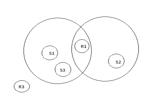
Transmission scope of node S1 Transmission scope of node S2

Fig 2.13Hidden and Exposed Terminal Problems
2.7 Proposed Work
The Basic motivation of our undertaking was to analyze and develop an Efficient Mac based DS-CDMA protocol for work outing near far job. A CDMA communicating system requires an efficient design and testing of its subsystems of PN-sequence generator, spectrum spreading and de-spreading digital circuits and digital modulator and detector faculties which give high throughput.
Another issue is near far consequence.
2.7.1 Reason for proposed protocol
The Near far consequence is created in the uplink of DS-SS CDMA. When a combination of unfastened and closed-loop power control which ensures that each terminus generates the same signal power at the base station. The base station monitors the power of standard signal from each terminus and instructs distant terminuss to increase their signal powers and nearby terminuss to diminish theirs illustration below shows the power control entirely is non plenty to cut down the near–far job in DS SS CDMA ad-hoc Network. Example: - Let denote the distance between nodes Ks and n. suppose A wants to pass on with B utilizing a given codification and C wants to pass on with D utilizing a different codification. Suppose that tap ? dCD, dCB & A ; lt ; & A ; lt ; tap, and dad & A ; lt ; & A ; lt ; dCD. Then, the MAI caused by C makes it impossible for B to have A transmittal. Similarly, the Multiple entree intervention caused by A makes it impossible for D to have C transmittal. It is of import to observe that the two transmittals can non take topographic point at the same time, irrespective of what transmittal powers are selected if an addition in power is made to battle the MAI at B, this increased power will destruct the response at D.
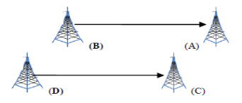
Fig 2.14Example shows the Power Control entirely is non plenty to cut down the Near–Far job in DS-SS CDMA Ad-hoc Network
The above Fig. unveils two types of jobs - .
1.Medium entree job: - The usage of two different distributing codifications to happen at the same clip is non possible for two transmittals, this job is referred to as medium entree job.
2. Power control job: - If the terminuss adjust their signal powers so two transmittals can take topographic point at the same clip so that the intervention caused by one transmittal is non big plenty to pulverize package response at other terminuss. This is referred as power control job.
So the cardinal solution to the close far job must hold both elements: power control and medium entree.
2.7.2 DESIGN GOAL FOR PROTOCOL
The Following are the specifications while planing a MAC protocol for Ad-hoc web:
- The operation of the protocol should be widen and provide quality of service for existent clip traffic.
- The protocol must be a non-synchronous, spread operation, every bit good as scalable for big webs. It must besides affect minimum exchange of information and must be suited for real-time execution.
- The protocol must be scalable to big web. in this protocol should be minimise the consequence of hidden and exposed terminus job.
- The protocol should hold agencies for adaptative informations rate control and it should hold power control mechanisms in order to expeditiously pull off the energy ingestion of node.
- The receiving system circuitry should non be complex in the sense that it should non be required to supervise the whole codification set.
So we design the DS-SS CDMA system with MAC protocol utilizing VHDL.
|
VHDL Implementation of DS-SS CDMA based Mac protocol for Ad-hoc Networks |
1 |
Cite this Page
Code Division Multiple Access Communication Systems. (2018, Jul 17). Retrieved from https://phdessay.com/code-division-multiple-access-communication-systems/
Run a free check or have your essay done for you
